MIB-100 Special Features
The duration of each inspection interval is determined by the length of time
that a particular color appears on the screen and finishes with an audio signal.
The duration for each inspection can be altered in 0.1-second increments by the
supervisor. The operator simply touches a button on the operator interface to
begin the inspection process. The operator interface indicates when the
inspection interval has expired by changing color. At the completion of the
inspection cycle the inspector can record whether the last sample passed or
failed the visual inspection. The PLC will keep the total number of containers
Accepted, Rejected and total number of inspections performed. The supervisor can
reset the data accumulation at the beginning of a new tray, batch or shift.
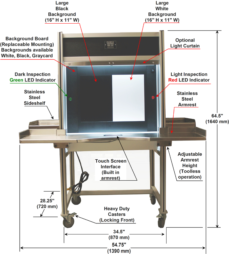
Figure 1. MIB-100DLC Key Components of Production Model
The MIB-100DLC offers the latest design configuration in
the product line. The system is based on the standard MIB-100™ framework
with several unique features. The "D" option refers to a digital control
added to the PLC that allows the user to change the light intensity within the
inspection volume by simply entering desired value on the operator interface.
This feature is useful when inspections mandate different intensity levels for
different products. The user can change from 2000 Lux to 6500 Lux with a
few entries on the keypad. There is an optional "Programming Selector
Switch" mounted behind a locked door to prevent unauthorized light intensity
changes.
The "LC" option refers to the addition of light curtains
in front of the White and Black backgrounds. The LC option will
automatically start the countdown of the PLC Pacer function when the inspection
holds the product in the inspection volume. If the product is removed
prematurely from the inspection volume prior to reaching the zero time of
countdown timer then the inspection cycle must begin again before moving to the
next step of the sequence. The LC option requires that the product be be
positioned in the inspection volumes for the proper durations, thus improving
inspection consistency. This option can be used in combination with the
2-position footswitch to record Pass/Fail count of containers, useful in the
reconciliation of defective units.
The MIB-100™ is fabricated with an anodized aluminum framework and
black
polycarbonate panels. The panels have a dual purpose; first to shroud the
inspection samples from ambient light and second to insure the proper background
is available for the inspection. The electronic components necessary for operation
are included as part of the standard MIB-100™ system
configuration,
including the lighting control systems
(with feedback circuitry), the Operator Interface (visual display), the electronic
pacer system and the LED visual
pacer indicators. The system can be ordered with the standard curved front
Corian© armrest, optional straight front Corian© armrest
or optional curved front stainless steel armrest. The placement of the
Operator Interface can be selected from Left, Center or Right sides of the
armrest.
NOTE: The
lamps selected for MIB-100™ provide approximately
6,000 - 10,000 hours of life1 in
which the intensity maintains an acceptable output level. The standard operating
procedure requires that the lamps be changed at least once a year. Normally the
lamp change is scheduled during the July or December shutdown period.
It should be noted that all lamps provided by Phoenix Imaging are short tested,
burned in for at least 100 hours and then measured to obtain the lamps initial
output intensity and given a unique serial number. When a Phoenix Imaging
Manual Inspection Booth is manufactured all the lamps are matched to specific
output, i.e. foot-candle. The initial lamp output is recorded on the
manufacturing label so that the lamps can be replaced with lamps of the same
output when necessary. This reduces the time required during the
calibration process, often no adjustments are required! Phoenix Imaging
stocks thousands of biax lamps for MIB customers and offer same day shipment if
ordered before 2:00 pm EST.
Available MIB-100™ Options
There are a number of optional components that can be
added to the MIB-100™ to aid the inspector and make the inspection task more
comfortable.
1) The "Visor Kit" offered on MIB-100™ Version 2.3 has
been superseded with the "Top and Bottom Blind" option on MIB-100™ Version 3.1
and above. The Top and Bottom Blind Option prevents the inspector from
direct viewing of the illumination sources or bright interior surfaces when the
lamps are positioned close to the front of the booth. There is minimal
decrease in light intensity in the inspection volume.
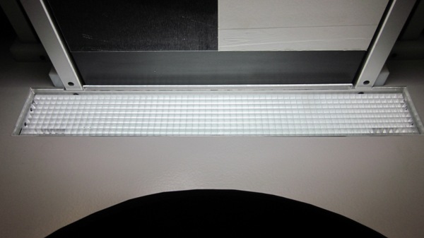
Figure 2 - Top and Bottom Blinds
2) The MIB-100™ booth can be raised or lowered by using the booth
hydraulic leveling kit to increase the center line on the inspection area by 12 inches,
helpful when booths are shared with inspectors of different statures. This is an electric assist unit so with the
push of a button will raise or lower the booth to the perfect height for each
inspector! The pump assembly is covered with a stainless steel shroud as
illustrated in Figure 3.
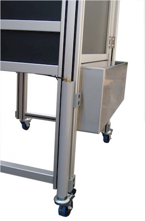
Figure 3 - Hydraulic Leg Lift Option
3) There is an audible alarm option that will provide
audible signals for pacing operations as well as the standard LED pacers.
The audible alarm can be turned on or off in software. There is a volume
control built into the audible alarm to adjust the level.
4) The optional Side Shelves Kit is very useful when the
MIB-100™ is used for high volume production work. The optional stainless
steel side shelves for
in-process product flow are
fabricated to hold customer product trays. The side shelves can be ordered
in fully adjustable or fixed configurations. The fully adjustable side
shelves have articulated joints that allow the trays to oriented in the most
comfortable position for the individual inspectors. The arms are articulated
and the joints allow the shelves to be positioned in almost an infinite number
of ways. The side shelves are designed to fit the size of the customer
holding trays.
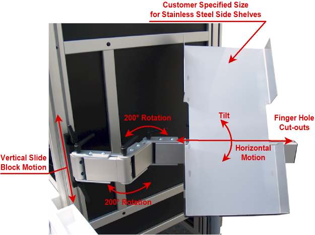
Figure 4. Adjustable
Stainless Steel Shelf
Figure 4 above illustrates the adjustment handles used to raise/lower and rotate
the shelf support arm. No external tools are required to make the
adjustments. When the handles contact the wall or structure simply lift
them toward the hex head screw and rotate them to a new position.
5) The Plastic Catch Basin is used to protect
the bottom mirror when the operator is inspecting large or heavy containers.
The trays holds 0.5 liters of fluid and will prevent protect from entering the
inspection booth in the event of an accident. The Catch Basin is
constructed of Acrylic plastic for durability and it will not impact the light
intensity. It is easy to clean with soapy water or IPA wipe.
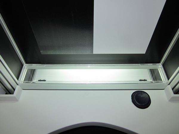
Figure 5 - Plastic Catch Basin to cover lower mirror plate
6) The foot switch option is use to start the inspection
cycle in place of touching the operator screen. It heavy duty construction
of this dual actuator foot switch is designed for millions of cycles.
There is a raise ridge between the two actuators to prevent accidental contact.
The foot switch has a 2 M cable and quick disconnect to the bottom of the booth.
7) New Stainless Steel Armrest is available with or
without Side Shroud Covers! (See Figure 1 for an example of the SS
Armrest).
8) Top Shroud with adjustable speed cooling fans.
This option is useful when the inspection booth will be used in an environment
in which the light is not controlled well. The Top Shroud minimizes the
effects of ambient lighting on the inspection process. To keep the
inspector comfortable there are dual fans with a speed control.
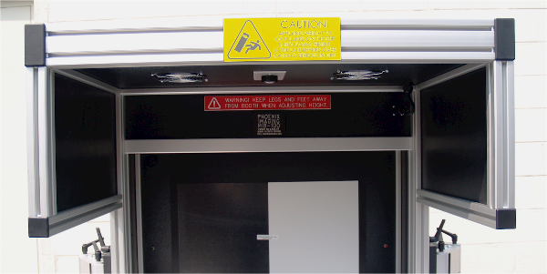
Figure 6 - Top Shroud with Cooling Fans
Illumination System Considerations
ILLUMINANCE: (old term: ILLUMINATION)
Definition: (density of luminous flux on a surface)
Symbol: E
Unit: Footcandle (fc) = (1 lumen per sq. foot)
Unit: Lux (lx) = (1 lumen per sq. meter)
EQUATIONS
Candela
Lamp Lumens
FC = ------------------------
FC = -----------------
Distance
square (ft.)
Area (sq.ft)
Candela
Lamp Lumens
LUX = ------------------------
LUX = ----------------
Distance square
(m.)
Area (sq. m.)
CONVERSIONS
FC = Lux x .0929
LUX = FC x 10.76 - (ie: 550 FC =
5918 LUX)
1 - Lamp life depends on intensity during use.
High intensity inspection requirements will have a shorter lamp life than low
intensity inspection requirements. Nominal use at 3750 Lux will provide
approximately 6,000 hours of use.
|