Front Cover Porosity Application Profile
As an OEM supplier to Chyrsler, Diversified
Machining (Howell, MI. recently purchased a part of a three plant deal from
UniBoring, Inc.), is a company adept at specialized precision machining,
assembly and inspection of powertrain products. To provide its customers with
quality, high-performance, and competitive products, Diversified precision
machines and assembles intake manifolds, cylinder heads, bedplates, covers and
engine blocks as well as partial and full engine assembly for niche and
production markets.
One of the high volume parts supplied to DaimlerChyrsler is
the Engine Front Timing Chain Case covers for both the 3.7L and 4.7L models.
These Engines are installed into DaimlerChrysler’s Jeep and Dodge vehicles at
seven Assembly Plants worldwide. To ensure the integrity of this part each
surface must be carefully examined for all cast and machined, deformities and
sealing face porosity defects. For this to be accomplished, they contracted
Phoenix Imaging (Livonia, MI; www.phoeniximaging.com) to develop a custom-built
image processing system.
The company implemented Phoenix
Imaging’s AVIS (automated visual inspection system) to perform multiple
operations including porosity inspection, presence of clear and/or tapped holes,
robot guidance and optical character recognition (OCR) for component
traceability. “Moving these inspection tasks from Human vision to robust
Machine Vision ensures defects won’t reach our Customers while providing
traceability into the Vehicle” says John Wagnitz, Quality & Manufacturing
Systems Mgr. The system inspects the front cover on a vertical pallet
conveyor. By holding the front cover in a vertical orientation both sides and
all features can be viewed at the same time.
“To perform an accurate inspection of the part,” says
Gerald Budd, President of Phoenix Imaging, “it is necessary to create software
that encompassed all of the desired inspection task. The task required porosity
inspection of the “A” and “D” faces, non clean up on all machined surfaces,
casting variations, presence of all through holes, presence of tapped holes and
traceability of every inspected component by means of optical character
recognition of indent marker serial number.
The application required multiple sensors of various pixel
resolutions. When initially developed the resolution of CCD sensors were large,
1300 x 1030 x 10-bit CV-M4+ Camera Link cameras from JAI Pulnix. This is small
when compared to the sensor sizes that are implemented in similar applications
of today. However, this technology established the standard for on-line
porosity inspection and demonstrated its use in a real world production
environment.
The application implemented a number of new technologies
created by Phoenix Imaging, several of which are patent pending. Every
successful vision application requires a well designed illumination system.
This is even more critical for surface inspection applications. Phoenix Imaging
manufactures over 300 different types of illumination systems.
We have designed a special illumination system that
could be implemented on-line and provide uniform illumination for viewing the
machined surfaces of the front cover. One of the most
difficult problems to overcome using such a system is to reduce the false
rejects due to surface contamination or machining operations. Phoenix
Imaging has developed a unique illumination system that reduces information from
surface anomalies.
The sensors are interfaced to the
company’s PC-based PVS-100 machine vision system using two CL1 frame grabbers
from Epix (Buffalo Grove, IL). The machined features of the component, i.e.
quality of irregular shaped surfaces, holes, and threads are inspected using
specific vision algorithms. The vision algorithms are created using the
company’s VisionMaker™ software. The software allows each of the inspection
algorithms to be developed and tested very quickly. The VisionMaker™ software
acts as a pre-filter to all of the company’s ACTIVE-X vision tools. The
software allows the vision developer to construct the vision algorithm as a list
of low level vision functions arranged to massage the image and prepare it
before being analyzed by the ACTIVE-X tool. Unlike many vision products, there
is no need to compile the vision algorithm before implementation. This allows
the vision developer (or trained user) to modify a vision algorithm in the
production environment without special computers, development tools or
libraries. According to Budd “VisionMaker™ allows us to generate and test
vision algorithms in minutes rather than hours.”
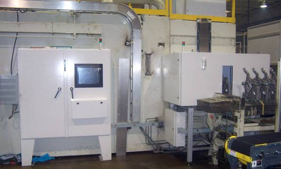
Figure 1. Complete AVIS Installation
Figure 1 shows the components
used in the Automated Visual Inspection System (AVIS) used by Diversified for
the DaimlerChyrsler 3.7 / 4.7 L Front Cover inspection. The main electrical
panel sits to the left with a large touch screen operator interface. The main
inspection enclosure housing sensors and lighting system is shown at the right.
The Front Covers are held in pallets and translate through the opening in the
middle of the inspection enclosure. A stack of checked parts appear at the
extreme right waiting robot pickup for placement is air decay leak testers.
The front covers move through the inspection system on a
pallet conveyor system. The inspection system acquires images of both sides of
the front cover simultaneously while being held on a transfer pallet. The
software first locates the position of the component within the field of view of
each sensor. It is important to compensate for both component translation and
rotation because the pallet may experience ware and tear during normal use.
After components are located, a number of inspection zones may be applied to
specific regions. Each inspection zone can apply its unique inspection
criteria. The inspection system can perform tasks that human inspectors find
difficult, including the ability to accurately measure the size of
imperfections, count the total number of imperfections, determine the density of
imperfections per unit area, and determine the proximity of imperfections with
respect to each other.
Using the M4 medium resolution cameras, it was possible to
check for porosity defects of <1mm with a field of view of about 400 mm x 400
mm. The large format or high resolution cameras
allow the machine vision engineer to use one camera in the place of four or more
cameras simplifying both system setup and calculations. The resolution of a
machine vision system can be determined by the ratio of the number of pixels in
the sensor to the field of view (FOV). Cameras with a pixel resolution of 1300
x 1030 to 2000 x 1600 are considered as medium resolution formats. Cameras with
a pixel resolution of 3000 x 2000 or greater are currently considered to be a
high-resolution format. Budd further states that the latest generation system
has demonstrated the ability to detect porosity < 400µm on a 500 mm long
automotive component using an 8 mega-pixel camera. There are even larger format
cameras in the development pipeline.
In order to perform the inspection of features in other
regions of the casting six (6) 752 x 582 x 8-bit CV-M50 low-resolution (Pulnix-JAI)
cameras are used. The low-resolution cameras were interfaced to second PVS-100M
using three (3) SV5 frame grabbers from Epix. The inspection system is designed
using a modular format in which one image processor acts as the “Cell Master”
and additional image processors serve as “Slave” devices. The image processors
communicate with each other using a high-speed Ethernet link, 100MB/s or 1
GB/s. Figure 2 below illustrates the basic system configuration for
multi-processor inspection system.
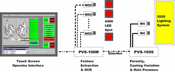
Figure 2. Basic System Configuration
The main program is called the Automated Visual Inspection
System (AVIS). AVIS acts as the main nerve center of the inspection system. All
inspection parameters, tolerance limits, and results are displayed through
AVIS. The operator interface is generated using Microsoft Visual Studio,
usually programmed in VisualBasic. The VisualBasic environment is preferred
because it allows us to rapidly customize screens to meet specific customer
requirements.
The actual inspection process starts on a “Viewport”, this
is a screen that displays the image as acquired from an individual sensor. Each
sensor requires at least one Viewport on which the live or processed images are
displayed. The image processing tools used to perform the actual inspection
tasks are provided in an ACTIVE-X format. The specific tools required for each
task may be added by simply dragging and dropping them on the Viewport. The
ACTIVE-X toolset includes utilities for alignment, blob characteristics, curve
fitting, etc., that permit the developer to select the functions that can be
used individually or together to measure the specific features of a component.
In this application the Phoenix Imaging team developed a system that could be
used to classify specific defects in a number of zones, each with a specific set
of requirements.
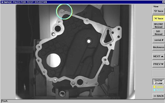
Figure 3. Screen shot highlighting the suspect area that failed inspection
Figure 3 is representative of an example log file of a
component that failed one of the inspections. The file is labeled with the
serial number of the component and indicate the type and location of flaws by
drawing a circle around the defect location. This method was selected so that
the defect was obscured by graphics and the image could be examined at a later
time. Every front cover has a serial number indent marked on the neck in the
machining process. The mark is positioned so that it can be identified in “Car
Position” and read by the OCR software during the inspection process. Every
image acquired by the inspection is archived on DVD using the serial number.
The archive database includes images of “Accepted” and “Rejected” components.
The database can be used to verify the condition of an individual product as
tested just prior to shipment to the customer. The technology developed for
this project has demonstrated unique inspection and traceability capabilities
and is patent pending.
A typical system
with a cost between $200k
and $400k can pay for itself
in less than a year. When you consider the cost
of onsite sorting after a suspect products enters the production stream
costs associated with such as system become
immediately justifiable. Human inspection has been
shown to be about 70% effective at best, an online AVSIS™ will provide
consistent inspection capability and will never require a break.
|