The size of the porosity that can be detected is a function of the sensor resolution. The system works best when the resolution of the image elements (pixels) remains square. This allows the system to accurately measure size, shape and displacement between features or defects. Phoenix Imaging PVSIS™ will work with a number of image sensors but prefers to use sensors with at least 3000 pixels in the line width for accurate height measurements. A typical system will provide 25 to 50-micron resolution in the x & y directions and better than 5 microns in the z-direction. The images generated using either scan technique is generally very large in size. A 500 mm scan at 50µm will be 3,200 pixels wide and 10,000 lines in length and generate a grayscale image of several megabytes and a z-height image of 20 megabytes or more. The images are very large and require special image processing computers to acquire, process and analyze the images. The image processor used in the PVSIS™ is capable of processing these large images very quickly, a large 10,000-line image in less than 2 seconds. These images are too large to transfer over the standard factory data network for displaying the resultant images are stored on the Middle-Man 2™ system.
The PVSIS™ system implements highly specialized image process algorithms to ensure that the porosity isolated is real. The system first finds the primary surface in the scanned image and then aligns the relevant inspection mask. The inspection masks are developed using CAD and are usually defined by the customer. There may be more than one inspection mask per scan, a primary and a secondary, each with their own inspection criteria.
The Phoenix Imaging image processing technique is unique in that we only identify porosity as “suspect” regions when the feature lies below the primary surface plane. The system will ignore most stray marks or discoloration on a surface when it has no depth. Porosity must have a minimum depth in order to be considered as a “suspect” region. The minimum depth is determined by the customer but a typical depth for porosity is about 200µm below the surface.
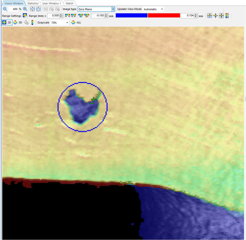
The image above indicates the primary surface (yellow-orange area) and the porosity as having depth (blue area) below the surface. Part of the side wall of the casting is also visible as blue area.
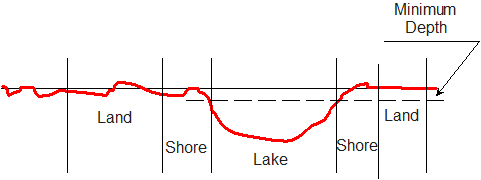
The typical profile of porosity is best described as a lake on a plane. The surface under inspection is normally a flat region and porosity is a depression in that region. It is easy to think about porosity as a lake in a flat region surrounding it. In the diagram below the flat region is the “Land” and the “Lake” represents the porosity. There is a area between the Land and the Lake called the Shore. The Lake begins after the Shore. The normal variation in the Land (or the metal surface) may experience changes in depth, but these are less than the depth of the Lake (porosity).
The example below illustrates a line drawn through a typical region with porosity. The minimum depth of the porosity is selected below the Shoreline and the major axis is measured from shoreline to shoreline.
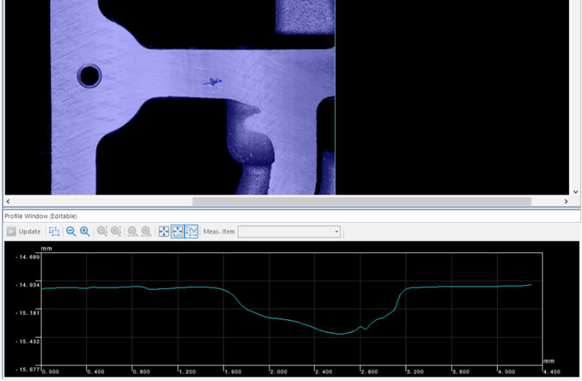
Profile of porosity
Comments are closed