Porosity Inspection on Machined Metal Components
Cylinder Deactivation Plate
Among the most useful in this area is porosity
inspection on machined metal components, primarily aluminum and precision
die-cast magnesium castings. When
cast components are machined the fresh cut often exposes sub-surface porosity
that can affect the performance of the sealing surface. Phoenix Imaging
has developed and patented several technologies to perform this inspection task
effectively at a reasonable cost to the customer. The system has been
implemented for a number of customers since early 2001. A case history is
presented in the Porosity Application tab for one of those customers.
Porosity applications can be performed on a wide range of
components and sizes. The basic porosity applications implements one of
the Phoenix Imaging Tunnel Illumination Systems designed to match the size of
the component. The objects range in size from 50 mm square to 1,000 mm x
800 mm required for engine blocks or cylinder heads. The image show below
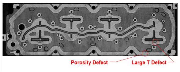
is a cylinder deactivation control plate. Although it is not the largest
it is of the typical size found in automotive applications. This image was
taken with a medium resolution sensor (8 Megapixel) and has been reduce here to
minimize download time. The plate is about 450 mm long x 180 mm wide.
Cylinder Deactivation Control
Plate
The samples must be clean and dry in order to perform the
inspection. However there most likely will be some variations in the
surface texture or color. The AVSIS system is capable of ignoring the
variations in apparent brightness and enhance the isolation of the surface imperfections
by performing a unique set of vision algorithms. The image processing
reduces the common features found in the image to extract the features that are
different.
The Porosity Defect circled above has a typical shape and contrast. The defect
is enlarged in the image below so that the defect is easier to see. There
is a large percentage of the sealing area with discoloration that is considered
to be of acceptable surface quality that the AVSIS™ system must ignore. It
is easy to see in this image why other surface inspection systems often fall
when attempting to use global thresholding techniques.
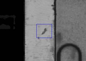
Enlarged Porosity Defect
The grayscale values of the defect are illustrated as
red characters in the image at the right.
Notice the variations in surface texture in the image
above and grayscale pixel map. It is easy to see that the "good" area of
the surface is not uniform in grayscale intensity and that a specialize vision
algorithm is required to extract the defect for it's surroundings.
Most porosity inspection applications are part of an
in-line process. Depending on the size of the component to be inspected
the the material handling technique will change. The cylinder deactivation
control plate shown above is a fairly high volume component (>750,000 units per
year) and requires a handling system to keep pace with those volumes.
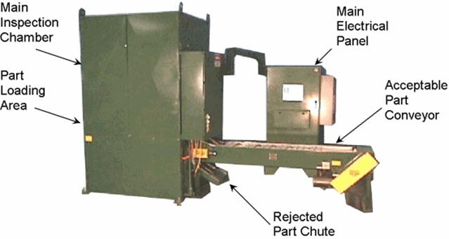
The picture above is the lift & Carry system used to
perform the inspection of the cylinder deactivation control plate.
Components are loaded into the left side by a robot, automatically alignment and
moved to the inspection chamber. The instrument enclosure is fairly tall
to accommodate the illumination system and to minimize optical distortion.
A second station in the size enclosure actually determines whether al of the
threaded holes have been tapped. If the component is judged acceptable
then it moves along the "Acceptable Part Conveyor" and is automatically packed.
If the component is deemed unacceptable then it is sent out via the Rejected
Part Chute.
We have performed surface inspection on a wide range
components and would be happy to evaluate your component using a reduced scale
version of the technology. Phoenix Imaging has an extensive laboratory for
the evaluation of customer applications to determine if this technology is the
correct solution for your organization.
|